Ultrasonic Testing: What You Need to Know

Ultrasonic Testing: What You Need to Know

When the need arises to inspect, test, and evaluate a material, component, or assembly without compromising its serviceability, non-destructive testing (NDT) in the best approach.

Non-destructive testing is a set of inspection methods and procedures used to interrogate parts with minimal intervention and with the aim of preserving their condition.

Ultrasonic testing (UT) is one of the most widely used branches of NDT that uses high-frequency sound to reveal hidden flaws and measure thickness without harming components.

In this article, we will explore ultrasonic testing, its history, mechanics, advantages, and limitations. Keep reading to learn more…
 

What is ultrasonic testing?

At its simplest, ultrasonic testing is a fast, flexible non-destructive evaluation method that uses high-frequency sound waves to examine materials for internal discontinuities, measure dimensions and, in some cases, infer material properties. 

The technique operates on the same physical principle as sonar and medical ultrasound. A transducer sends a short burst of ultrasound into a test object and records the returning echoes. Variations in the returned signal (timing, amplitude, and frequency content) expose the presence, location and, to an extent, the nature of anomalies.

UT spans a wide frequency range, usually between 0.1 MHz and 15 MHz, though specialised laboratory or microstructural studies can extend up to 50 MHz or more. Lower frequencies penetrate further but resolve less detail, while higher frequencies resolve smaller features but attenuate more rapidly.

So what makes UT a preferred evaluation method? Its primary industrial objectives are threefold:

  • Detection - UT locates internal defects such as cracks, voids, delaminations, and inclusions. 
  • Thickness measurement - UT provides reliable thickness readings through pulse-echo time-of-flight measurements, a routine requirement in corrosion monitoring and fabrication control. 
  • Specialised measurements - adaptations of ultrasonic methods can assess residual stress, measure bolt preload and characterise layered structures.

UT is inherently volumetric, inspecting the interior rather than only surfaces. It typically requires access to one surface and a means to transmit the ultrasonic wave effectively into the material, such as a liquid or gel couplant, although non-contact methods also exist. 

Success depends on selecting the right wave mode, frequency and technique for the material and geometry in question; proficiency, therefore, combines equipment knowledge with practical experience.
 

A history of ultrasonic technology

The history of ultrasonic testing is one of curiosity and iteration.

The earliest seeds were sown by developments in underwater acoustics. Sonar systems, developed and refined for detecting objects beneath the sea, showed that sound could reveal hidden structure across a medium that was otherwise opaque to sight. 

This insight led researchers and inventors to ask whether the same principle could be applied to solids and biological tissues.

During the late 1920s and early 1930s, a number of investigators published experimental work and patents exploring ultrasonic interrogation of solids. 

In 1929, Soviet physicist M. Sokolov reported experiments studying ultrasonic methods for detecting metal inclusions and boundaries, while other experimenters explored using paired transducers to transmit and receive through a solid specimen. In 1931, Mulhauser obtained a patent that described detecting flaws using two separated transducers. 

These early efforts established two core ideas: 

  • High-frequency sound propagates through solids, that discontinuities scatter or reflect energy.
  • Measuring those responses could provide useful information about unseen features.

A crucial advance was the shift from continuous-wave approaches to pulsed operation. Continuous-wave methods can detect changes in transmission but are limited in locating depth. 

Pulsed systems, by contrast, send a short broadband burst and measure the time taken for echoes to return. Time-of-flight information immediately provides a depth coordinate, opening the door to practical thickness measurement and internal flaw sizing.

In the 1940s American researchers formalised pulse-echo techniques for solids. Firestone and Simons produced significant work that led to patents and practical devices. Firestone’s 1942 patent described transmitting high-frequency vibrations into a workpiece and determining the time interval of reflected vibrations to locate flaws. 

The earliest instruments presented their signals in A-mode, a simple trace showing amplitude versus time on an oscilloscope. This was transformational. A “blip” on the screen could be correlated directly with the presence and depth of a reflector inside the material.

The introduction of B-mode extended capability by rendering echoes as a two-dimensional, grey-scale image. A-mode remained invaluable for simple thickness checks and rapid field work, while B-mode brought improved visualisation for more complex geometries and, eventually, for rudimentary imaging of defects.

As instruments improved through the 1960s and early 1970s, the sensitivity of UT increased to the point where ever-smaller flaws could be detected.  But a surge in rejection rates and an impractical intolerance for minute, non-critical anomalies presented a problem.

The rise and maturation of fracture mechanics offered a solution. By predicting whether a discontinuity of a given size would remain stable under expected loads, engineers could shift from the uncompromising “no defect” stance to a “damage tolerant” design philosophy. 

This approach accepted existing flaws, provided they are characterised accurately and remain below critical dimensions for the expected loading conditions.

Implementing damage tolerance required quantitative information. That requirement fuelled the development of quantitative non-destructive evaluation (QNDE), an engineering and research discipline that blends signal-processing methods, calibration protocols, fracture mechanics, and reliability assessment. 

QNDE elevated ultrasonic practice. Waveform analysis, beam modelling, and calibration standards became as important as the hardware itself.
 

How does ultrasonic testing work?

Ultrasonic testing relies on a few physical principles, but applying them properly in the workshop or the plant requires practical judgement and an understanding of how waves behave in real materials.
 

Transducers and piezoelectric materials 

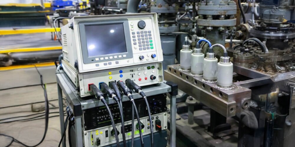
At the core of any ultrasonic instrument is the transducer, within which sits a thin crystal or ceramic element with piezoelectric (the ability to generate an electric charge when mechanical stress is applied) properties.

When an electrical pulse is applied, the element changes shape and produces a short burst of mechanical vibration. When a returning mechanical vibration strikes the element, it generates an electrical signal. 

Common materials include natural quartz and engineered piezoceramics such as lead zirconate titanate (PZT). Transducer design (element thickness, backing material, matching layers and housing) determines the centre frequency, bandwidth and sensitivity, and therefore the trade-off between resolution and penetration.
 

Couplant and energy transfer 

Sound cannot jump efficiently from a transducer into a solid if an air film intervenes. 

The acoustic impedance mismatch causes reflection and severe signal loss. A couplant (a light oil, glycerol-based gel or water) fills the microscopic gaps between probe face and part surface to allow efficient transmission. 

The choice of couplant matters. Viscosity, wetting behaviour, and temperature stability affect signal fidelity and inspector convenience. For periodic or remote inspections, water squirter systems or immersion tanks are used to maintain consistent coupling, although non-contact alternatives exist for cases where couplants are undesirable.
 

Pulse-echo timing and flaw localisation 

Most UT relies on time-of-flight information. A short broadband pulse is sent into the part, where the instrument measures the time elapsed until an echo returns. 

Knowing the wave speed in the material allows conversion of that time to a distance. For example, the distance to a reflector and back is given by the product of half the time-of-flight and the known sound speed.

Accurate depth sizing requires correct velocity data, which can vary with alloy composition, heat treatment and temperature. Hence, good practice includes measuring the longitudinal and shear wave speeds in representative test pieces or using calibration blocks traceable to standards.

Reading an A-scan 

An A-scan displays received signal amplitude as a function of time. 

The first significant trace corresponds to the transmitted pulse (the initial excitation), and subsequent peaks indicate reflections from internal features or the back wall. 

In a defect-free specimen of uniform thickness, the backwall echo typically appears at a predictable time. A defect generates an earlier echo, its relative amplitude, and time delay give clues to size and depth.
 

How do ultrasonic waves interact with materials? 

Three interactions determine UT performance:

  • Reflection and scattering - when an ultrasonic wave encounters a boundary between materials with different acoustic impedances, a portion of the energy is reflected toward the transducer. Perfectly planar, perpendicular interfaces give strong specular echoes, while rough or inclined discontinuities scatter energy more diffusely.
  • Refraction and mode conversion - at interfaces where the incident beam is not perpendicular, waves change direction according to Snell’s law for acoustics. In solids, an incident longitudinal wave can convert partially to shear motion at the boundary.
  • Attenuation and dispersion - as waves travel, they lose energy through absorption and scattering. The loss of clarity increases with frequency and with microstructural anomalies such as coarse grain, porosity or micro-cracking. Dispersion can alter wave shape and complicate timing measurements, especially over long paths or in anisotropic materials.
     

Wave modes

Different wave motions are suited to different inspection challenges:

  • Longitudinal waves - particle motion is parallel to propagation. These travel fastest and move through solids, liquids, and gases. They are well suited to thickness gauging and to detecting volumetric defects at normal incidence.
  • Shear (transverse) waves - particle motion is perpendicular to propagation. Shear waves only exist in solids and are slower than longitudinal waves. They are particularly valuable for weld inspection and for detecting planar flaws such as cracks because they can provide higher sensitivity to such discontinuities when used with an appropriate angle beam.
  • Surface (Rayleigh) waves - confined to the near-surface region, surface waves decay exponentially with depth. They detect surface and just-below-surface defects and characterise near-surface layers.
     

What methods and techniques are used in ultrasonic testing?

The choice of method used in ultrasonic testing depends on the component geometry, material, defect types sought, and the operational constraints.
 

Basic testing methods 

There are two basic signal modes that govern most ultrasonic work:

  • Pulse-echo mode - a single transducer transmits a short pulse and then receives echoes from internal features and the far surface. This is the default for thickness measurement and for locating reflectors from a single-access surface. It is flexible, simple to deploy, and provides time-of-flight information that converts directly to depth when sound speed is known.
  • Through-transmission (attenuation) mode - this uses separate transmitter and receiver transducers placed on opposite sides of the workpiece. The receiver measures the transmitted energy, and an attenuation or local loss of signal indicates a discontinuity that interrupts or scatters the beam. Through-transmission can detect poorly reflective defects that give little backscatter, but it requires access to both sides of the part and provides no direct depth coordinate without scanning geometry or additional processing.
     

Application techniques 

There are a number of application techniques applied to ultrasonic testing:

  • Contact testing - the most common field technique. The probe is placed in direct contact with the part using a couplant. Contact testing supports straight-beam inspections for thickness checks and angle-beam inspections for welds and crack detection.
  • Immersion testing - the component, transducer or both are immersed in water which serves as the couplant. Immersion testing produces consistent coupling and enables automated scanning with high repeatability.
  • Air-coupled and non-contact techniques - allows inspection without liquid couplants, valuable where contact is impractical or damaging. It commonly operates at lower frequencies to accommodate the larger impedance mismatch and attendant attenuation. Electromagnetic Acoustic Transducers (EMATs) generate ultrasonic waves without a liquid couplant by using magnetic fields and Lorentz forces, and are especially useful for hot surfaces, rough finishes or coatings and for avoiding surface preparation.

Additionally, there are a number of advanced UT techniques used in more niche scenarios:

  • Phased array ultrasonic testing (PAUT) - PAUT arrays consist of many small elements that are pulsed with programmable time delays to steer, focus and sweep the sound beam electronically. This capability enables rapid sectorial scans, improved probability of detection of complex flaws and greater control over beam incidence.
  • Time-of-flight diffraction (TOFD) - TOFD uses a transmitter and a separate receiver set apart along the weld line. Rather than relying on specular reflection, TOFD records diffracted wave energy from crack tips. The arrival times of these diffracted signals permit precise sizing of crack height and estimation of growth rate under service loading.
  • Full matrix capture (FMC) and total focusing method (TFM) - FMC records all element-to-element transmit-receive combinations in an array. Post-processing with TFM synthetically focuses the data across a region of interest, producing high-resolution, near-diffraction-limited images that improve detectability of complex-shaped defects.
  • Guided wave ultrasonics - Guided waves expand along a structure and can travel many metres, enabling rapid screening for defects at remote or inaccessible locations.
     

Data display formats and what they mean 

The data received from these techniques and methods are commonly displayed in formats known as A-scan, B-scan, C-scan, or S-scan. Understanding the differences between these formats is key to evaluating the results.

  • A-scan - the basic single-channel display of amplitude versus time. A-scans are compact and ideal for thickness checks and simple front/back-wall identification.
  • B-scan - a two-dimensional cross-sectional view (profile) produced by plotting A-scan amplitude along a linear scan, B-scans reveal the depth and approximate planar extent of reflectors in the scanned plane.
  • C-scan - a plan (top-down) map showing the distribution of reflected amplitude, time-of-flight or derived thickness across an area. C-scans are useful for corrosion mapping and for presenting inspection results in an accessible visual format.
  • S-scan - common in phased-array instruments, the S-scan (sectorial scan) displays a fan-shaped image produced by electronically steering an array. It provides a convenient view to assess weld geometry and detect inclined defects.

Interpreting displays often requires combining views. For example, a PAUT S-scan plus a TOFD record gives both angled-sector sensitivity and precise tip sizing. 


Why is ultrasonic testing useful?

Ultrasonic testing occupies a central place in industrial inspection because it combines sensitivity, adaptability, and safety. 

But at the same time, it is not a universal remedy. Let’s look at the principal strengths of ultrasonic methods with the practical constraints that shape their use in production, maintenance, and research.
 

The advantages of ultrasonic testing

The widespread adoption of ultrasonic testing is a testament to the myriad benefits of the method.

Ultrasonics interrogates the material volume, not merely the surface. The pulse-echo principle yields direct depth information, so defects may be located within a component rather than only indicated on its exterior. For many serviceability decisions, knowing the depth and approximate geometry of a reflector is more important than merely detecting its existence.

Shear waves and focused beams are particularly effective at detecting and sizing planar discontinuities such as cracks and lack-of-fusion in welds. When correctly tuned, ultrasonic methods can reveal small but critical flaws that may escape other inspection types.

Modern portable ultrasonic instruments combine rugged construction with fast, on-site measurement. This means that one can obtain thickness readings, locate discontinuities and deliver a preliminary assessment in minutes.

Unlike radiographic inspection, ultrasonic testing uses non-ionising sound waves and therefore does not require radiation protection measures, reducing regulatory burden and simplifying logistics.

From basic A-scan thickness checks to phased-array sectorial sweeps and FMC/TFM imaging, ultrasonic techniques scale across complexity levels. Phased-array and advanced post-processing provide refined spatial resolution and allow inspections that would have been impractical or impossible with early single-element instruments.

Although initial capital for high-end arrays and processing systems can be significant, ultrasonic testing frequently offers a good return on investment. Through reduction in unscheduled outages, more targeted repairs and the ability to track defect growth quantitatively, it enables condition-based rather than time-based interventions.
 

The limitations of ultrasonic testing

However, the limitations cannot be ignored.

Ultrasonic inspection is an interpretive skill. Probe placement, wedge selection, beam orientation and gain settings all influence results. Effective inspections require trained, certified personnel and reliable procedures.

Conventional contact UT requires good surface contact and a clean interface. Rough surfaces, corrosion scale, heavy paint or coatings, and complex surface geometry can all impede coupling or scatter energy, reducing detectability.

Additionally, certain materials present intrinsic difficulties. Coarse-grained metals, castings with large inclusions, and some stainless-steel castings scatter high-frequency energy and raise the noise floor. Composite materials, while often inspected ultrasonically in manufacture, may require specialised techniques and can present complex mode conversions that complicate interpretation.

Although pulse-echo needs only single-side access, complex geometries, tight radii and confined spaces can make it hard to maintain consistent probe orientation and coupling. Through-transmission requires two-side access, which may be impractical for in-service structures. Guided-wave methods address some access problems but introduce interpretation complexity.

Higher frequencies increase spatial resolution, but attenuate more rapidly. The trade-off sets a practical limit on the smallest detectable defect at depth. In very thick sections, or where attenuation is high, inspectors must accept lower resolution or adopt alternative modalities.

Conventional contact UT depends on a couplant. In freezing temperatures, high surface temperatures, or hazardous environments, maintaining adequate coupling is challenging. EMATs and air-coupled techniques reduce or remove couplant dependence, but have their own limitations.

Lastly, no single UT mode perfectly determines all defect parameters. Fitness-for-service decisions must account for measurement uncertainty and typically rely on conservative acceptance criteria, corroborative inspection or repeatability studies.
 

The Lab: home of non-destructive testing

When you need to inspect, test and evaluate a material, component, or assembly without destroying its serviceability, then you’ll want to make use of The Lab at Brookes Bell’s metallurgical survey, inspection, and non-destructive testing services.

The Lab brings together the world’s finest state-of-the-art equipment and technologies with highly-experienced experts to provide the very best inspection and testing services in the industry. 

For more information, contact our team today for an obligation-free consultation.

Discover non-destructive testing at The Lab

For more of the latest news, information, and industry insights, explore The Lab’s News and Knowledge Hub

Thermoset vs Thermoplastic: What’s the Difference? | Self-Healing Superhydrophobic Coating Delivers Unmatched Quality | What Metals Are Non-Ferrous?


Author
Andrew Yarwood
Date
08/01/2026
You are currently offline. Some pages or content may fail to load.